


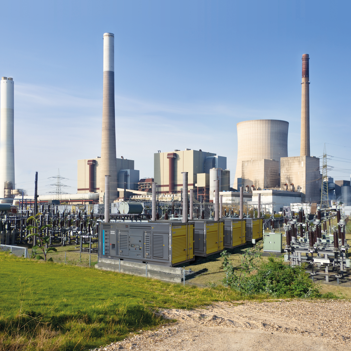
Ask a plant engineer at a combined cycle station what happens if the instrument air goes away and you will get a very short answer. Valves go to fail position. The unit trips. Somebody writes a report. That is the whole reason a power plant treats its air system differently than a factory does: in a factory, losing air stops production, and in a power plant, losing air can put the unit on the grid operator's phone.
So when we talk about compressed air for power plants, we are really talking about two separate systems that happen to share a compressor room. Get that distinction right and everything downstream gets easier.
Two Air Systems, Two Different Specs
Every generating station, whether it burns gas, coal, biomass, or runs water through a turbine, ends up with an instrument air population and a service air population. They are not the same and they should not be treated the same.
Instrument air feeds control valve actuators and positioners, damper drives, pneumatic transmitters, solenoid pilots, and on nuclear units, power operated relief valve operators. It is dry, it is clean, and in most plants it is the one that cannot go away.
Service air, sometimes called plant air or station air, feeds soot blowers, ash handling and pneumatic conveying, filter pulse cleaning, air tools in the maintenance shop, hose stations on the turbine deck, and purging. It tolerates a lot more. A refrigerated dryer and ordinary particulate filtration is usually enough. We go deeper on that side in service air for soot blowing and ash handling, including how to size the ride-through for a full sequence.
Plants that run one system for both end up doing one of two wasteful things: treating soot blower air to instrument quality, or letting instrument air drift down to service quality. The first one costs money forever. The second one costs you a unit trip, once.
The Spec That Actually Governs Instrument Air
ANSI/ISA-7.0.01-1996, Quality Standard for Instrument Air, is the document most plants write into their specs. Three numbers do the heavy lifting.
| Parameter | ISA 7.0.01 limit | What it means on the floor |
|---|---|---|
| Pressure dew point | At least 18F below the lowest ambient any part of the system sees, and never above 39F at line pressure | Outdoor headers in a northern plant push you to a desiccant dryer at -40F |
| Particle size | 40 micron maximum in the air stream | That is the system floor. Positioners and small pilots usually want tighter, so add point of use filtration |
| Oil content | 1 ppm w/w maximum, liquid and vapor combined | A well built treatment train on a lubricated screw meets this. Lubricant still has to be checked for compatibility with elastomers in your positioners |
Note what the standard does not say. It does not say you must buy an oil free compressor. It says total oil has to stay under 1 ppm and the lubricant has to be compatible with the devices it will reach. Plenty of stations meet that with a lubricated rotary screw compressor and a proper filter and dryer train. If you want a fuller explanation of the class system that sits alongside this, our ISO 8573-1 breakdown covers it.
The Dew Point Trap Nobody Catches Until January
Here is the mistake we see most often on power station air, and it is always the same story.
The instrument air header leaves a heated compressor building, runs outside along a pipe rack to the boiler house, and drops into a valve gallery. Somebody sized a refrigerated dryer for it because the compressor room is 70F year round and a 38F dew point looked fine on paper.
Then it gets to 5F outside and the moisture in that header condenses and freezes in the low point of the rack. Now you have a damper drive that will not stroke and nobody can figure out why, because the dryer is running fine and the dew point gauge in the compressor room reads 38F.
ISA 7.0.01 is written to prevent exactly this. Read it as a metal temperature rule, not an ambient rule. The lowest temperature any part of that piping will ever reach sets your dryer, and outdoors in most of the country that means a desiccant dryer at -40F pressure dew point on the instrument air side, with a refrigerated dryer on service air where the piping stays inside.
Sizing: Base Load Is Boring, the Transients Are Not
Instrument air demand on a running unit is remarkably flat. Actuators hold position, positioners bleed a little, and the number barely moves. Service air is the opposite: soot blowing sequences, ash conveying cycles, and baghouse pulse cleaning all hit hard and stop.
Practical sizing approach:
- Meter the instrument air header first. Do not estimate it from a device count. Most plants find the real instrument air number is far smaller than the installed compressor capacity, which is why the compressors run unloaded half the time.
- Size service air on the transient, not the average. A soot blowing sequence or an ash conveying cycle can double plant demand for a few minutes. That is a storage problem more than a horsepower problem, and the soot blowing and ash handling guide walks through the calculation.
- Buy storage instead of the next size compressor. A wet receiver ahead of the dryer and a dry receiver near the transient load is far cheaper than another 50 hp. Four to six gallons per cfm is a reasonable starting point for a screw based system, and more where the hits are big and short. Our air receiver tanks cover both positions.
- Do not lift system pressure to fix a local problem. If one ash conveying line wants 120 psi and the rest of the plant wants 90, that line gets its own storage or a booster. Every couple of psi across the whole plant is roughly one percent on the power bill, and you already know what that number looks like at station scale.
Redundancy: What N+1 Should Actually Buy You
The usual arrangement on the instrument air side is two compressors running and one in standby, which is how Oconee ran its instrument air system for years and how most stations still lay it out. That part is well understood.
What gets missed is redundancy downstream of the compressors. A very common setup is redundant prefilters and afterfilters feeding a dual tower dryer, and people call that a redundant train. It is not. If the shared dryer goes down, or the interconnecting piping has a single point, you have redundant filters feeding a single failure. If instrument air is genuinely a cannot-lose system for you, the redundancy has to carry all the way through dryer and piping, not stop at the filter housings.
Three more things worth building in:
- A backup connection between service air and instrument air, with a check valve and a filter or dryer skid, so service air can feed the instrument header in an emergency and not the other way around.
- Dedicated instrument air storage sized to hold the header up long enough to get the standby machine started and loaded, or to bring the unit down in a controlled way.
- A dew point alarm on the instrument header that goes to the control room, not a gauge somebody reads on rounds.
Where We Can Help and Where We Cannot
Straight answer, because it matters for a station buyer.
Balance of plant and service air is squarely in our lane. Rotary screw packages, refrigerated and desiccant dryers, filtration, receivers, condensate handling, piping, and the parts to keep all of it running. Same for gas turbine peakers, biomass plants, hydro stations, and the maintenance shop side of any station.
What we do not do is safety-related nuclear procurement. If you are buying for a safety-related instrument air system inside a nuclear station's quality program, that equipment carries 10 CFR 50 Appendix B and NQA-1 pedigree requirements and a commercial grade dedication process that we are not set up for. Buy that through a qualified supplier. Non-safety balance of plant air at the same station is a normal commercial purchase and we can absolutely quote it.
Maintenance Items That Bite Power Stations Specifically
Ash and fly ash in the intake. On coal and biomass units the compressor intake is often in the worst possible air. Move it, duct it from a clean side, and expect to change inlet filters far more often than the manual says. A loaded inlet filter raises discharge temperature and pushes oil carryover up, which is how a 1 ppm instrument air system quietly stops being one.
Desiccant that never gets checked. A heatless dryer with a failed valve will still look like it is working and will still show a green light. The tell is a dew point spike on load swings. Instrument the dryer, do not trust it.
Condensate that goes where nobody looks. A station makes a lot of condensate, and at a plant with an NPDES permit an oily discharge is a compliance problem, not a housekeeping problem. Run it through an oil water separator and keep the records.
Leaks on a vibrating plant. Thousands of fittings, constant vibration, thermal cycling. Twenty to thirty percent of production lost to leaks is normal and it is the cheapest capacity you will ever recover.
Frequently Asked Questions
Does instrument air have to come from an oil free compressor?
Not by ISA 7.0.01. The standard sets a total oil limit of 1 ppm w/w and requires that whatever lubricant is present be compatible with the pneumatic devices it reaches. A lubricated rotary screw with a correctly sized separator, coalescing filter and carbon stage meets that in practice. Some owners specify oil free anyway as a policy matter, which is a legitimate choice, just not a code requirement.
What dew point should the instrument air header run?
At least 18F below the coldest temperature any part of the system will see, and never above 39F at line pressure. If the header runs outdoors, that means desiccant drying to -40F in most climates. If it stays entirely inside a heated building, a refrigerated dryer is fine.
Can service air back up instrument air?
Yes, and it is a common design, but only one direction. Put a check valve and a dedicated filter and dryer on the tie so service air can feed the instrument header without service air contamination migrating in during normal operation. Never let instrument air feed soot blowers through the same tie.
How much storage does a station need for soot blowing?
Enough to ride through the sequence without dragging header pressure below what the control valves need. Meter the actual draw and duration of one sequence, then size a dry receiver near that load to cover it. This is almost always cheaper than adding compressor capacity that sits unloaded the other 23 hours a day.
Is a piston compressor ever right for a power plant?
For a small hydro station, a peaker that runs a few hundred hours a year, or a maintenance shop, yes. For a base loaded unit where air runs continuously, no. Continuous duty is what rotary screws are built for and what pistons are not.
Where to Start
If you are rebuilding a station air system, do it in this order: split instrument air from service air on paper, meter both, set the instrument header dew point from the coldest metal temperature in the run, then size compressors and storage to what you measured. Most of what goes wrong with compressed air for power plants traces back to treating one system as if it were the other.


